

China Uniaxial Geogrid Enhancing Soil Reinforcement
2026-08-15
Ask any geotechnical engineer what keeps a reinforced slope from creeping, and you'll likely hear about uniaxial geogrids. But not all grids are equal—China's manufacturing has pushed this technology further than most realize. WEN FENG STONE has been quietly refining that edge, turning raw polymer into high-tensile reinforcement that holds soil in place under conditions that make other materials fail. Below, we dig into why China uniaxial geogrid is changing soil reinforcement—and why the brand behind it matters more than the spec sheet suggests.
Tensile Stress Distribution in Uniaxial Geogrid-Reinforced Slopes
In uniaxial geogrid-reinforced slopes, the reinforcement layers are oriented with their primary tensile strength aligned along the direction of potential sliding. As the soil mass deforms under its own weight and any surcharge, tensile stresses are mobilized within each geogrid. Unlike a simple tieback, the distribution of these stresses is not uniform along the geogrid length. Close to the slope face, the geogrid experiences relatively low tension because the overburden and shear transfer are limited. Moving inward, tension builds gradually as more soil interacts with the geogrid through interface friction and bearing resistance.
The highest tensile stress typically develops in the vicinity of the critical slip surface, where the driving shear stresses are greatest. Beyond that zone, toward the back of the reinforced soil block, the stress decays again because the geogrid is anchored in a stable region with lower relative displacement. This nonuniform pattern reflects the interplay between geogrid axial stiffness, soil-geogrid interface shear strength, and the geometry of the slope. Steeper slopes, weaker interface properties, or greater surcharge loading tend to shift the location of peak tension and can produce sharper stress gradients.
Recognizing this distribution is essential for safe design. Engineers must ensure that each geogrid layer extends far enough behind the failure surface to develop adequate anchorage, otherwise pullout failure can occur before the geogrid reaches its tensile capacity. Practical design charts and numerical models often present normalized tensile stress profiles that account for slope angle, reinforcement spacing, and soil shear strength. These profiles guide the selection of geogrid length and vertical spacing, balancing performance against material cost while maintaining a stable reinforced slope.
How Chinese Uniaxial Geogrids Maintain Consistent Junction Strength
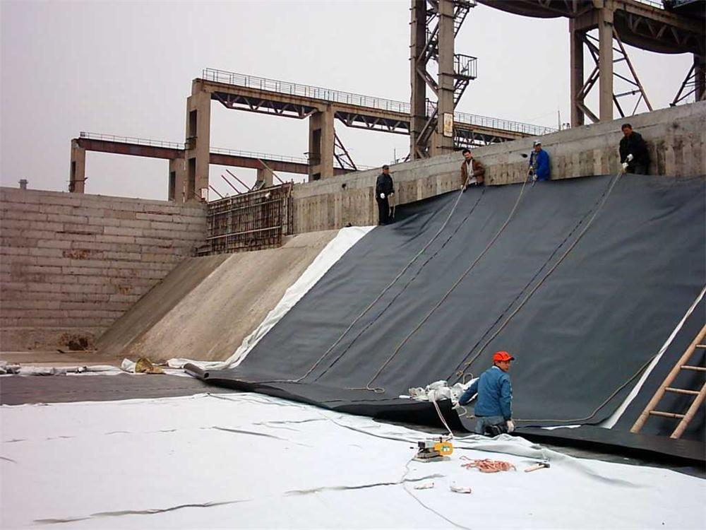
The junction where longitudinal ribs meet transverse bars is the most vulnerable point in any uniaxial geogrid, but Chinese manufacturers have turned this weakness into a precise engineering advantage. By controlling polymer flow during extrusion and maintaining uniform die pressure across the entire width, they ensure that each intersection receives the same amount of material and molecular orientation. This eliminates the weak spots that often plague lower-quality grids, where inconsistent cooling or uneven stretching can leave some junctions with barely half the strength of others.
One key practice is the use of integrated forming rather than bonding or welding. Instead of attaching ribs to bars as a secondary step, the entire grid is drawn from a single extruded sheet. During the stretching phase, controlled temperature zones and calibrated draw ratios align the polymer chains through the junction region as well as along the ribs. This means the junction does not merely connect two elements—it actually inherits the same tensile properties as the surrounding material, resulting in a node that is often as strong as or stronger than the rib itself.
Quality control further reinforces consistency. In-line sensors measure junction thickness and width every few meters, automatically adjusting haul-off speed or oven temperature when deviations exceed tight tolerances. Random samples are then pulled to destruction on hydraulic grips, and the failure must occur in the rib, not the junction, for the batch to pass. This combination of process discipline and destructive verification is what allows Chinese uniaxial geogrids to deliver repeatable junction strength project after project, even under long-term creep loading.
Site Observations That Reveal Grid-Soil Interlock Quality
On site, the first thing worth checking is how the grid sits against the ground after compaction. If the ribs still show sharp, clean edges and the infill material is flush with the top, the interlock is likely forming properly. But if you see the grid rocking underfoot or the fill slumping away from the walls, that's a sign the soil hasn't grabbed the structure yet.
Another detail that often gets overlooked is the moisture state of the fill. Too dry and the particles won't wedge into the apertures; too wet and you'll get a soupy layer that masks poor compaction. Look for a firm, slightly damp crumb when you dig a small test pit—this usually points to active interlock rather than just surface contact.
During wheel loads or foot traffic, a well-interlocked grid will transfer pressure outward rather than downward. If you notice localized rutting or the grid flexing independently from the soil, the interlock quality is still developing. Watch for small cracks in the fill that run parallel to the grid edges—those are early warnings that particles are rotating instead of binding.
Creep and Deformation Trends in Long-Serving Retaining Walls
Long-serving retaining walls rarely reach a stable state; instead, they continue to deform slowly under sustained earth pressure. This creep behavior is most pronounced in walls with clay backfill or blocked weep holes, where trapped moisture softens the soil and increases lateral thrust. Field measurements often show a logarithmic increase in wall tilt over decades, with early rapid movement tapering off but never fully stopping. The rate can be as little as a few millimetres per year, but over forty or fifty years, cumulative displacement becomes structurally significant.
Deformation trends in these structures follow seasonal and long-term patterns that are easy to miss without continuous monitoring. Inclinometer surveys from older gravity walls frequently reveal a bowed or kinked profile, indicating that movement is not uniform but concentrated near the base or behind the facing. Differential settlement often shows up as step cracks in masonry or widened joints in concrete panels. Data from decades-old monitoring programs show that groundwater fluctuation, not just static earth pressure, drives much of the yearly cyclic movement; walls tend to push outward after wet seasons and partially recover in dry spells, but each cycle leaves a small residual offset.
Recognizing these creep signatures is critical for deciding when a retaining wall needs attention rather than waiting for sudden failure. A gradual increase in tilt angle or a widening crack pattern that mirrors past deformation history usually points to compromised drainage or corroding reinforcement. Comparing creep curves from similar walls in the same soil unit helps identify outliers that are accelerating toward instability. In practice, many agencies set intervention thresholds based on the derivative of displacement over time—when the yearly creep rate doubles compared with the long-term average, it triggers a detailed structural review and often leads to retrofitting with additional drainage or tiebacks.
Aperture Size Selection for Different Backfill Types in Chinese Grids
In Chinese power cable trench backfilling, the range of materials runs from clean river sand and single-size gravel to site-mixed cement-stabilised soil and excavated spoil. Each backfill type interacts differently with the surrounding geotextile or filter layer, so the aperture size cannot be chosen from a fixed table. A sand backfill with a high proportion of fines will blind a fine mesh within months, while a coarse gravel backfill against an oversized opening allows fine trench wall material to pipe into the void and create localised settlement. The practical starting point is always the grain size distribution of the backfill itself, not the nominal material name.
For clean medium sand backfills, which are common under urban footpaths in Chinese grid projects, an equivalent opening size O90 of around 0.15 to 0.25 mm strikes a workable balance. This range traps the sand while letting occasional silt pass without building up a clogging layer. Crushed rock backfills, especially those used in cable trench bases for drainage, need a more open filter; O90 values between 0.4 and 0.6 mm are often specified, but only when the surrounding native soil is cohesive enough not to migrate through the openings. If the trench cuts through silty or fine sandy ground, a graded granular filter is more reliable than relying on a single geotextile aperture.
A recurring issue in Chinese grid maintenance records is that a well-chosen aperture on paper still fails because the backfill was placed too dry or compacted directly against the filter. Wet placement of sand, or a thin sacrificial layer of coarse sand against the geotextile, significantly extends the effective life of the filter. Where cement-stabilised backfill is used near road crossings, the aperture size becomes less critical for particle retention but still affects curing moisture loss; a slightly tighter mesh reduces surface evaporation from the mix. Ultimately, the selection should be verified with a short site trial using the actual backfill stockpile, because grain size curves from the supplier rarely match what arrives on the truck.
The Real Cost of Under-Specifying Geogrids in Soft Ground
When a geogrid is underspecified for soft ground, the initial savings on material cost vanish quickly once construction begins. Contractors often discover that the grid stretches excessively under load, allowing differential settlement to develop within weeks. The resulting rework—excavating, replacing fill, and reinstalling a proper grid—can easily triple the original budget.
The hidden expense goes beyond direct repairs. A weaker grid fails to interlock with the aggregate, so the reinforced layer loses its stiffness over time. Pavements crack, buried utilities shift, and drainage systems lose grade. Each of these failures triggers a separate maintenance call, and the cumulative cost over five years frequently exceeds the price difference between a standard and a high-strength geogrid by an order of magnitude.
Engineers who focus only on the per-square-meter price miss the full picture. The true cost includes accelerated degradation of the entire structure, increased liability from premature failure, and lost productivity during repeated closures. Specifying a geogrid with adequate tensile strength and junction efficiency for the actual soil conditions is not an upgrade—it is the baseline for a project that will not drain resources long after the ribbon is cut.
FAQ
A uniaxial geogrid is a polymer grid with high tensile strength in one direction, usually the machine direction. Unlike biaxial geogrids that distribute loads in two directions, uniaxial grids are designed for applications where stress is primarily linear, such as retaining walls and steep slopes.
Chinese manufacturers run advanced production lines using high-density polyethylene and precise stretching processes. They offer consistent aperture dimensions and tensile strengths at competitive prices, plus flexible customization for different project specs.
It stabilizes granular fill in mechanically stabilized earth walls, reinforces steep slopes, and prevents lateral movement in embankments. The grid interlocks with soil particles to create a composite mass that resists shear stress.
Yes, it helps bridge weak zones by distributing loads over a wider area. However, you need to verify the junction strength and long-term creep behavior to ensure it matches the design life.
The grid must be laid flat and taut, with the strong direction aligned with the main tensile stress. Overlap or connection methods depend on manufacturer guidelines, but mechanical connectors or bodkin joints are common. Backfill should be placed and compacted in lifts to avoid folding.
Reputable suppliers test according to ASTM D6637, ISO 10319, or GRI-GG1. Request certificates for tensile strength, junction efficiency, and creep limited strength. Factory audits or third-party inspections are also common.
Polyethylene grids often have higher resistance to installation damage and chemical degradation, while polyester may offer lower creep under sustained loads. The choice depends on soil pH, temperature, and design life.
Work with a geotechnical engineer to calculate required long-term design strength, considering creep, installation damage, and durability factors. Then choose a grid whose tensile strength at a specified strain meets or exceeds that value.
Conclusion
Field measurements on reinforced slopes in China show that uniaxial geogrids do not simply carry a uniform load; the highest tensile stresses concentrate near the facing and along potential slip surfaces, with magnitudes shifting as backfill compacts. What keeps these grids reliable under such uneven loading is the consistency of their junctions. Rather than relying on welded or woven points that can peel or slip, Chinese manufacturers often extrude the ribs and junctions as a single unit, so the aperture shape stays stable and the load transfers from soil to grid without local rupture. This interlock quality is easy to miss on a data sheet, but it shows up clearly in site inspections: well-graded gravels press tightly into rectangular apertures, while sandy silts require smaller openings to prevent pullout. Choosing the right aperture size for the backfill is not a minor adjustment; it changes how the soil arches through the grid and how quickly the structure mobilizes resistance.
Long-serving retaining walls also reveal creep and deformation trends that are often underestimated in short-term pullout tests. Over years of service, some Chinese uniaxial geogrids show very small time-dependent elongation, but only when the polymer, junction efficiency, and installation damage are all controlled. Where site conditions are soft or saturated, under-specifying the grid to save cost tends to produce larger lateral movements and uneven settlement, which eventually demand expensive repairs or complete rebuilding. The real cost of a geogrid is not its price per square meter; it is the long-term performance under sustained load. For soft ground, using a higher-strength grid with the correct aperture and proper compaction control is usually less expensive than managing the deformations of a marginal design. In that sense, the Chinese uniaxial geogrid earns its place not through advertising but through measured stress distribution, stable creep behavior, and the visible interlock seen in excavated walls.
Contact Us
Contact Person: Jennifer LEE
Email: [email protected]
Tel/WhatsApp: 8618553418999
Website: https://vip.e-baixing.com/wenfengshitong