

Custom Shell Mold Casting: The Complete Guide to Precision Metal Parts
2026-11-16
Precision metal parts don’t happen by accident—they come from a process that balances detail, cost, and repeatability. Custom shell mold casting often sits in that sweet spot, yet many engineers overlook it. This guide breaks down how it works, where it shines, and when it’s the wrong choice. If you’re chasing tighter tolerances without the tooling sticker shock, Zhaoyuqi has been refining this exact approach.
What Makes Resin-Coated Sand Shells So Predictable
Predictability starts with the coating process itself. The resin is applied in a measured layer so each grain gets the same amount of binder, eliminating the random weak spots that often show up in ordinary sand molds. When the shell is formed and cured, the cross-linking reaction proceeds at a known rate, giving the shell a consistent hardness and gas permeability from batch to batch.
Another factor is the shell's dimensional stability. Because the resin-coated sand is pre-coated and then blown onto a heated pattern, the shell builds up in near-identical layers. There is no guesswork about how thick the shell will be in tight corners or flat sections. That repeatability means foundries can set their pouring parameters once and trust the mold to behave the same way every cycle.
Finally, the thermal behavior of resin-coated sand shells is well understood. The resin breaks down at a predictable temperature, releasing gases in a controlled manner. This creates a stable metal-to-mold interface, so casting defects like veining or gas porosity are easier to anticipate and prevent. The result is less scrap and fewer surprises during solidification.
The Shell Mold Process, Without the Guesswork
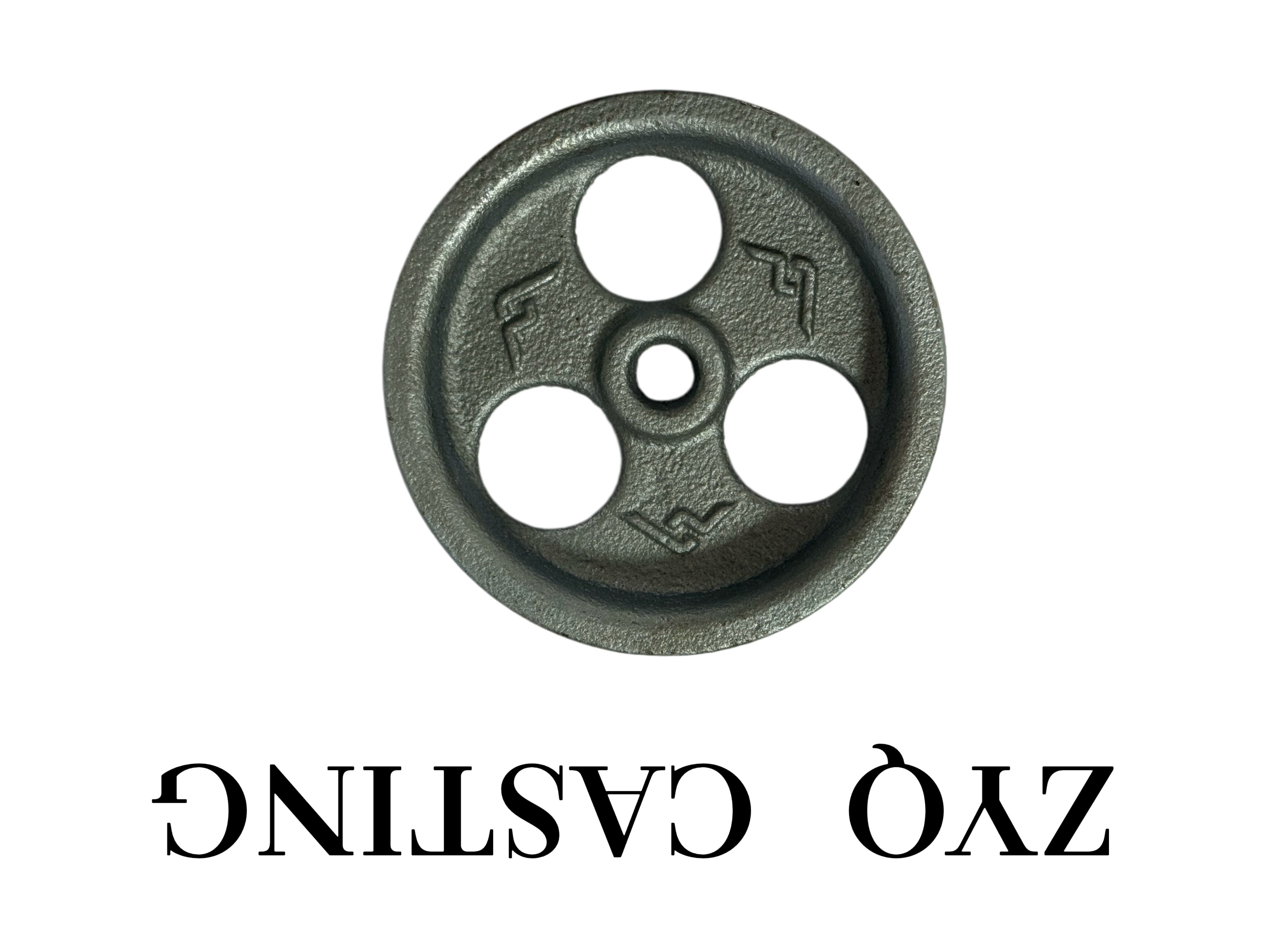
Shell molding strips away much of the unpredictability found in traditional sand casting. The process starts with a heated metal pattern, typically maintained between 230°C and 315°C, onto which a resin-coated sand mixture is blown or dumped. Within seconds, the resin melts and bonds the sand grains into a thin, hard shell that captures every contour of the pattern. Because the shell forms against a precisely machined pattern and cures under controlled heat, dimensional consistency from one mold to the next is astonishingly repeatable.
What really removes the guesswork is the elimination of moisture and loose sand variables that plague green sand methods. The dry, free-flowing resin sand doesn't compact unevenly or shift during pattern removal. Ejection pins and careful pattern design allow the two shell halves to release cleanly, then they're glued or clamped together for pouring. You know the cavity volume, the wall thickness, and the surface finish before metal ever enters the mold—there's no hoping the sand will hold its shape.
That predictability pays off in tighter tolerances and less post-cast cleanup. A well-tuned shell line can hold ±0.005 inch per inch on many features, and the smooth cavity surface routinely delivers 125–250 RMS finishes without extra coatings. Once the process parameters are locked in—pattern temperature, dwell time, sand chemistry—it becomes a highly stable production method, week after week, shift after shift.
Picking Alloys That Hold Sharp Edges and Fine Detail
The ability to keep a keen edge and reproduce fine geometry depends heavily on the alloy's hardness, grain structure, and work-hardening behavior. Many machinists and bladesmiths default to high-carbon tool steels like O1 or A2 because they take a razor edge yet still respond well to honing. However, if you need extreme wear resistance for intricate profiles, powder metallurgy steels such as CPM-10V or ZDP-189 offer a much finer carbide distribution, letting you sharpen a crisper line without the edge crumbling under pressure.
What often gets overlooked is how the material behaves during the actual shaping process. A coarse-grained alloy might hold an angle initially, but it tends to micro-chip when you're cutting fine bevels or engraving delicate patterns. Look for alloys that are either very clean in their ingot form or designed for low retained austenite after heat treatment. Simple alloys like W2 or 1095 can surprise you with their crispness, while certain stainless grades like AEB-L achieve an almost surgical sharpness because the carbides are so small they don't interrupt the edge line.
Practical testing beats spec sheets every time. If you're comparing candidates, do a simple push-cut test on thin paper or carve a tight radius in softwood. The alloy that leaves the cleanest entrance and exit marks, without visible tearing or rolled burrs, is the one that truly holds fine detail. Remember that edge retention isn't just about hardness numbers; it's about how uniformly the steel deforms under load. Sometimes a slightly softer alloy with an extremely homogeneous structure will outperform a harder but more brittle option when you're working at the limit of what the edge can support.
Designing Features That Avoid Common Casting Flaws
Rounded transitions and generous fillets do more than improve appearance—they steer molten metal through the mold without creating turbulence or cold shuts. Sharp internal corners act as stress risers and also interrupt flow, leaving voids or weak planes. Replacing a tight 90-degree junction with a radius of at least one-third the wall thickness gives the material a smoother path, while slightly tapering vertical ribs prevents premature solidification at the base. These choices don't just ease filling; they reduce the need for post-cast grinding and repair.
Uniform wall sections are often overlooked when a part has bosses, flanges, or mounting pads. A thick pad next to a thin web cools unevenly, inviting sink marks or porosity. Instead of bolting on a bulky boss, consider a cored-out pocket underneath or a stepped transition that matches the surrounding wall within 20 percent. This keeps solidification fronts advancing at similar rates, so shrinkage feeds properly rather than pulling from visible surfaces.
Parting line and draft decisions also quietly dictate quality. Deep pockets with vertical sidewalls force the pattern to drag or tear the sand, leaving rough surfaces or inclusions. Adding two to three degrees of draft and orienting the deepest cavity parallel to the draw direction lets the pattern release cleanly. Similarly, placing a heavy section near the gate rather than at the far end allows the riser to feed it fully, avoiding the classic flaw of an isolated hot spot freezing before liquid can reach it.
Tolerances and Surface Finish: What to Actually Expect
When a drawing calls for ±0.01 mm on every hole and Ra 0.8 on every face, the quote often comes back with a price that makes the whole project look absurd. It’s not that shops can’t hit those numbers—they absolutely can—but the effort jumps sharply once you leave the comfortable middle ground. On a typical CNC milled aluminum part, ±0.1 mm is almost free; ±0.02 mm means slower feeds, more tool changes, and maybe a CMM check. Similarly, Ra 3.2 is a natural result from standard milling, but Ra 0.8 usually forces a second finishing operation like fine boring or grinding. So before you tighten anything, ask whether that surface actually seals, slides, or sits in a precision assembly.
Material and process set the realistic floor. FDM prints drift by ±0.3 mm regardless of what the CAD says; SLM metal parts warp during build; thin turned parts spring out of the chuck. You can chase microns, but you’ll either pay for post-processing or end up with scrap. Surface finish runs into the same physics: turning gives you Ra 1.6–3.2 without drama, cylindrical grinding gets you to Ra 0.2–0.4, and lapping or superfinishing below Ra 0.05 is a different budget line entirely. If the part isn’t a bearing race or a sealing face, Ra 1.6 will likely look and perform fine.
One thing drawings rarely communicate is that tolerances and surface finish dig into each other. Polishing a bore to Ra 0.2 removes material and can push a tight diameter out of spec; holding a dimension to ±0.005 mm might force cutting parameters that leave a rougher surface than you wanted. Experienced designers tend to mark only the functional fits and critical faces with tight values, and leave the rest at shop-floor defaults. A hole that takes a dowel pin gets H7, a face that holds an O-ring gets Ra 0.8, and the outer cosmetic surfaces get Ra 3.2. That’s usually enough to make the assembly work without making the machinist hate you.
Real Components That Rely on Shell Mold Casting
Turbocharger turbine housings are a classic example—they face extreme thermal cycling and need precise internal volute shapes. Shell mold casting delivers the necessary surface finish and dimensional accuracy, which cuts down on post-casting machining and helps maintain exhaust flow efficiency.
Hydraulic valve bodies and pump housings also lean on this process. The internal passageways are often too intricate for conventional sand casting to reproduce cleanly, but shell molds hold fine detail and create smoother walls, reducing fluid turbulence and improving system response.
In heavy equipment and rail applications, gearbox casings and differential housings are routinely shell mold cast. The method handles the larger mass while holding tight tolerances across repeat production runs, so assemblies fit together without excessive hand fitting or secondary operations.
FAQ
Shell mold casting uses a thin, rigid shell made from resin-coated sand instead of a packed sand mold. Because the shell is formed against a heated metal pattern, it captures finer details, holds tighter tolerances, and gives a smoother surface right out of the mold. Custom simply means the shell and pattern are built specifically for your part geometry, rather than using an off-the-shelf mold.
It handles ferrous and non-ferrous alloys well. Common choices include carbon steels, low-alloy steels, stainless steels, ductile iron, aluminum, and copper-based alloys. The process is especially useful when you need precision in steel or iron parts that would otherwise require heavier machining after sand casting.
Shell mold casting typically holds linear tolerances around ±0.005 in/in or better depending on part size and geometry. Surface finish often lands in the 125–250 RMS range without secondary processing. That is noticeably cleaner than green sand casting, which reduces cleanup time, machining stock, and scrap.
It shines in the small-to-medium range, usually up to about 30–50 kg (65–110 lb), though some foundries push higher. The shell itself is thin, so extremely large or bulky parts may not be practical. However, for complex brackets, levers, gear blanks, impellers, and valve bodies, it is often a better fit than either sand casting or investment casting.
Investment casting offers finer detail and thinner walls, but it costs more and has size limits. Shell mold casting gives a good balance: better precision and surface finish than sand casting, but lower tooling and piece costs than investment casting for many medium-precision steel or iron components. It is a practical middle ground, not a replacement for every high-detail part.
You typically need a metal pattern plate, often made from aluminum or cast iron, which is heated during the molding process. This pattern can be single or multi-cavity depending on your volume. For custom orders, the pattern is machined to your part's exact dimensions, including draft angles and machining allowances, so the upfront cost is higher than loose sand molding but pays off in repeatability and finish.
Yes. Shell mold castings respond well to normalizing, quenching and tempering, annealing, and surface treatments. Because the as-cast surface is already smooth and near net shape, machining is often limited to critical bores, faces, and threads. Many customers specify shell mold casting precisely to cut down on post-cast machining hours.
Provide a fully dimensioned drawing or 3D model, the alloy grade, required quantity, surface finish or coating needs, and any critical tolerances or testing requirements. Mention if you need heat treatment, machining, or NDT like magnetic particle or ultrasonic inspection. Clear notes on draft, parting line preferences, and where machining stock is acceptable help the foundry build a pattern that fits your process instead of forcing you to adapt later.
Conclusion
Resin-coated sand shells bring a level of predictability that standard sand casting rarely achieves. The pre-coated grains bond under heat to form a rigid, dimensionally stable mold, so the metal cools against a consistent surface instead of shifting loose sand. This removes much of the guesswork from shell mold processing: patterns are heated to a set temperature, the sand is blown or dumped over them, and the shell cures in seconds. Because the mold is thin and hollow, it can be handled, inspected, and even stored before pouring, which helps foundries hold tolerances that would otherwise drift between shifts. The result is a repeatable route to precision parts without the cost of die casting.
Alloy choice matters just as much as the mold itself. Copper-based and aluminum alloys with good fluidity and low shrinkage tend to reproduce sharp edges and fine detail, while high-silicon aluminum variants resist hot tearing in thin walls. Designers who avoid abrupt section changes, deep untapered pockets, and overly long unsupported cores sidestep the most common casting flaws such as gas pockets, cold shuts, and distortion. Realistic expectations help too: shell mold surfaces typically land around 125–250 microinches Ra, and linear tolerances of ±0.005 inch per inch are common, though local features like holes or slots may need extra stock. From valve bodies and pump housings to gear blanks and impellers, shell mold casting keeps proving itself in components where a machined-from-solid approach would be wasteful and conventional sand casting too loose.
Contact Us
Contact Person: Nico Yin
Email: [email protected]
Tel/WhatsApp: 8618561567088
Website: https://www.ductileironparts.com/