

Push Pull Connector Manufacturer Shares Key Design Considerations for Reliable Connections
2026-11-21
Most push-pull connector failures don't start with a dramatic snap. They start quietly — with a contact that shifts just enough, a shield gap that opens under flex, or a strain relief that looks fine until the cable moves. Reliable connections are designed, not assumed. That’s why the team at REUNION focuses on the less obvious details behind mating cycles, vibration, and long-term contact stability. Here are the key design considerations they watch before a connector ever reaches production.
Contact Wiping Action That Keeps Mating Surfaces Clean
Most connectors rely on static contact pressure alone, but the wiping action built into this design changes how mating surfaces interact during insertion. As the pin enters the socket, the contact spring deflects slightly and slides across the surface rather than simply pressing into place. That sliding motion scrapes away dust, oxide layers, and thin films of contamination that would otherwise remain trapped between the two conductors.
The benefit shows up most clearly in field environments where connectors get unplugged and reconnected under less-than-clean conditions. Each mating cycle performs a small self-cleaning operation, restoring a fresh metal-to-metal interface instead of leaving residue to build up over time. This is especially useful for low-voltage signals, where even a slight increase in contact resistance can introduce noise or intermittent failures.
Rather than adding extra seals, coatings, or maintenance steps, the wiping geometry leverages the insertion force already present. The contact surfaces stay cleaner through normal use, which reduces the need for aggressive cleaning solvents or repeated reseating to chase down a flaky connection.
Latch Retention Force Curves People Overlook
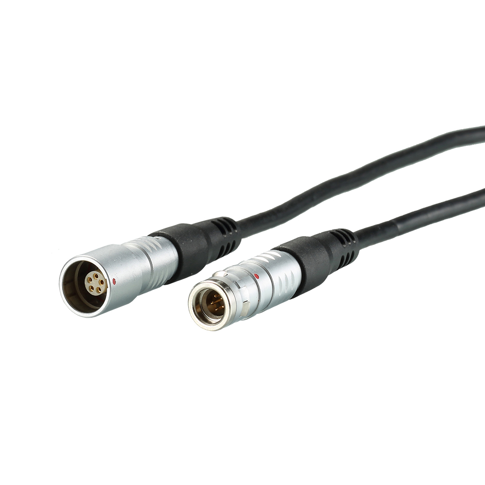
Most engineers glance at a latch retention curve, spot the peak force, and call it a day. That single number hides almost everything worth knowing. The slope before the peak tells you how the connector resists gradual seating misalignment, while the post-peak drop reveals whether the latch lets go cleanly or tears the contact plating on the way out. A curve that looks identical on a datasheet can behave completely differently in a vibrating housing, because the shape of the unloading path—not just the maximum—dictates how much energy gets fed back into the system.
There’s another detail that rarely makes it into summaries: the tiny plateau or knee that appears just before release. In many stamped latch designs, this flat spot marks the point where the retention dimple starts sliding across the mating ramp instead of digging into it. If the knee is too wide, you get a “sticky” disconnect that feels unpredictable to an operator and accelerates wear on the gold flash. If it’s absent, the latch pops off with almost no warning, which is why some field failures only show up after thermal cycling shifts the interference by a few microns.
What separates a useful retention curve from a decorative one is how closely the test fixture matches the real blade thickness, insertion angle, and plating condition. Push a latch into a polished steel coupon and you’ll get a beautiful, repeatable curve. Push the same latch into a slightly bowed PCB edge or a stamped housing rib with a burr, and the force curve develops a shoulder that no amount of peak-force averaging will catch. Reading the full trace—especially that overlooked region between initial contact and full engagement—shows whether the connector will survive assembly line variation or quietly fail after the warranty expires.
Grounding Paths Before Shielding Turns into a Fix
Most interference problems blamed on inadequate shielding actually begin further upstream, where return currents have no defined route. When a ground path wanders across a board edge or through a connector shell, the shield becomes an accidental conductor rather than a deliberate barrier. Checking continuity between chassis, cable screens, and reference planes usually exposes the real gap long before adding copper tape or swapping cables.
A useful habit is to sketch the intended current loop at low frequency and at the highest clock harmonic. If the drawn path crosses a seam, a split plane, or a pigtail, the grounding architecture is already compromised. Fixing those discontinuities tends to reduce emissions and susceptibility enough that the shielding decision becomes secondary. Shielding then supports a clean reference instead of masking a broken one.
Teams that skip this step often end up with enclosures wrapped in foil, multiple ferrites, and no clear explanation for why one unit still fails. The moment shielding is treated as the primary fix, the underlying return path problem remains hidden. Restoring a low-impedance ground connection first keeps the shield from being overloaded with currents it was never meant to carry.
Overmold Bonding for Flex and Sterilization Cycles
Bonding a thermoplastic overmold to a flexible circuit is rarely just about adhesion—it's about keeping that bond stable when the part is repeatedly hit with steam, vacuum, or chemical sterilants. Flex substrates and adhesives absorb moisture at different rates, and those small dimensional shifts can peel an overmold away from the polyimide or TPU layer long before visible damage shows up. Choosing an overmold resin with a matched coefficient of thermal expansion and low moisture uptake, then pairing it with a surface treatment that leaves no weak boundary layer, tends to outperform harder materials that only feel more durable on paper.
In sterilization cycles, the failure point often moves to the edges of the overmold where three materials meet: the flex circuit, the molded body, and whatever seal or connector sits nearby. Vaporized hydrogen peroxide and autoclave steam can wick into microgaps created by cooling stresses. A practical fix is to extend the overmold past the flex transition by a few millimeters and add a slight undercut or mechanical interlock rather than relying on chemical adhesion alone. This gives the bond path a longer, more tortuous route before any fluid reaches the conductors.
Process control matters as much as material selection. Mold temperature, injection speed, and preheating of the flex substrate all influence whether the melt wets the surface or freezes too early and leaves a cold joint. For multi-cycle sterilization, it is often better to run a lower melt temperature with longer hold pressure than to chase maximum throughput, because residual stress in an overmold can relax during the first few autoclave pulses and open the exact microgaps the design tried to avoid.
What Panel Cutout Tolerances Do to Mating Repeatability
Panel cutout tolerances rarely get the attention they deserve until a connector set starts fighting back. The opening in the panel sets the bounds for lateral and rotational movement before the mating halves ever touch. When the cutout is too tight, the connector sits exactly where the panel dictates, but any slight variation in the mating half or in the harness routing gets converted into contact stress. That stress tends to show up later as uneven wear, cracked housings, or intermittent continuity near the edges of the tolerance stack.
On the other end, a loose cutout offers freedom that sounds helpful but actually erodes repeatability. A connector floating in an oversized opening can shift a few tenths of a millimeter with every insertion. Over dozens or hundreds of cycles, the contact points wander, which changes insertion forces, fretting patterns, and ultimately the electrical signature. In high-pin-count or blind-mate applications, that drift is enough to turn a repeatable mating event into a lottery.
The useful range usually sits between those extremes, and it is rarely the nominal dimension that matters most. What counts is the allowed deviation across the full batch, because panels are punched, lasered, or milled with their own process spread. Controlling the cutout tolerance to match the mating pair's designed float keeps the connector centered enough for clean engagement, but not so constrained that it fights normal manufacturing variation. That balance is what lets mating repeatability hold up when the panels come off the line by the hundred, not just in a bench test.
Ingress Protection Without Making Unmating a Workout
Achieving a solid IP rating often means fighting with stiff seals and needing both hands plus a tool just to pull a connector apart. The real trick is designing the retention force so it stays dependable in wet or dusty environments, yet releases with a deliberate, one-handed motion. Instead of relying on brute friction alone, many modern designs use a short cam or lever action that converts a light squeeze into the extra mating force needed for a tight seal. This lets the connector shrug off moisture and debris while still letting a technician unplug it without bracing a foot against the panel.
Small geometric details make the difference between a secure snap and a wrestling match. A subtle ramp on the latch, paired with a silicone gasket that sits slightly proud of the housing, can create a progressive engagement: the seal compresses fully at the last moment, so the user feels a crisp confirmation instead of a vague, mushy resistance. Adding an asymmetric grip zone or a shallow finger groove near the release tab also helps, because it naturally guides the thumb into the right spot for a clean breakaway. The result is a connector that stays sealed when it should, yet never punishes you for doing routine maintenance.
Testing for this balance usually goes beyond just dunking the mated pair in water. Engineers cycle the connector hundreds of times while monitoring insertion and extraction force, looking for the point where seal wear causes the pull-out effort to creep upward. A well-tuned design keeps that curve nearly flat, even after exposure to dust, oil mist, or temperature swings. By treating unmating force as a first-class requirement alongside ingress protection, you end up with hardware that field crews actually like to use—quietly confident in its seal, but easy to separate when the job calls for it.
FAQ
The latching mechanism relies on spring loaded claws or balls that seat behind a lip inside the receptacle. Pulling on the cable only increases the locking force because the load is transferred through the latch rather than against it, so vibration and cable tugging do not easily break the connection.
Base contact alloys like beryllium copper maintain spring force after thousands of mating cycles, while gold over nickel plating protects against oxidation and micro-fretting. In harsh environments, selective gold on the mating area and tin on the termination end balances cost with stable resistance.
The cable exit is often the first failure point when a connector is pulled at an angle. A good design uses an internal collet or overmolded boot that grips the cable jacket, not just the conductors, and tapers the bend radius gradually to avoid stress concentration on solder joints.
Keying prevents a plug from being forced into the wrong receptacle and protects pins from bending. Some designs offer multiple keying angles or color coded shells so technicians can distinguish circuits instantly without needing a datasheet on site.
Sealing depends on both the shell interface and the cable entry. A silicone O-ring or gasket on the housing keeps moisture out during mated and unmated states, while an epoxy or grommet seal at the rear blocks ingress through the cable jacket. IP67 or IP68 ratings alone are not enough if the sealing surfaces are scratched or poorly lubricated.
Look beyond the catalogue rating. Harsh use can wear the latch springs and plating faster than laboratory cycles. Specifying a higher cycle connector can add cost, but choosing a replaceable insert or pre-wired pigtail can simplify maintenance when the connector is mounted in a difficult spot.
Both. The connector shell must create a 360 degree contact with the cable shield, usually through a metal clamp or conductive gasket. Any gap in that ring becomes a slot antenna and lets noise in or out, so the shell plating and the shield termination method matter as much as the cable braid itself.
Miniaturization increases contact density and reduces panel footprint, but it also raises heat concentration and makes the latch harder to operate with gloved hands. The sweet spot is usually a housing large enough for a firm grip and a cable bend radius that does not put excessive side load on the termination.
Conclusion
Reliable push-pull connectors depend more on subtle mechanical details than on catalog ratings. The wiping action designed into the contact geometry does a lot of the long-term reliability work: each mating cycle scrapes the contact surfaces enough to clear light oxides and dust without creating excessive wear. That balance becomes harder to hold when latch retention force is ignored. The force curve across the travel of the latch, not just the final locked value, determines whether operators feel a confident snap or a vague seat. Grounding deserves attention before shielding problems appear, because once a connector is installed, adding a separate drain path usually means reworking the panel layout or accepting a taller mating stack.
The same thinking applies to the cable exit and the panel interface. Overmold bonding has to survive repeated flexing and, in medical or lab equipment, aggressive sterilization cycles; a bond that passes a visual check can still peel at the edge after enough thermal shock. Panel cutout tolerances are equally easy to underestimate. A connector that mates cleanly on a bench can become intermittent when the cutout is slightly oversized or off-center, because the housing shifts just enough to change contact normal force. Ingress protection should not punish the user either. Well-designed seals and latch geometry keep water and dust out while keeping the unmating force reasonable, so the connection stays easy to operate after years of field use.
Contact Us
Contact Person: Hayley Liang
Email: [email protected]
Tel/WhatsApp: +86 13480625451
Website: https://www.reunion-china.com/