

Rubber Tire Tread Cooling Production Line Solutions That Improve Quality and Throughput
2026-11-16
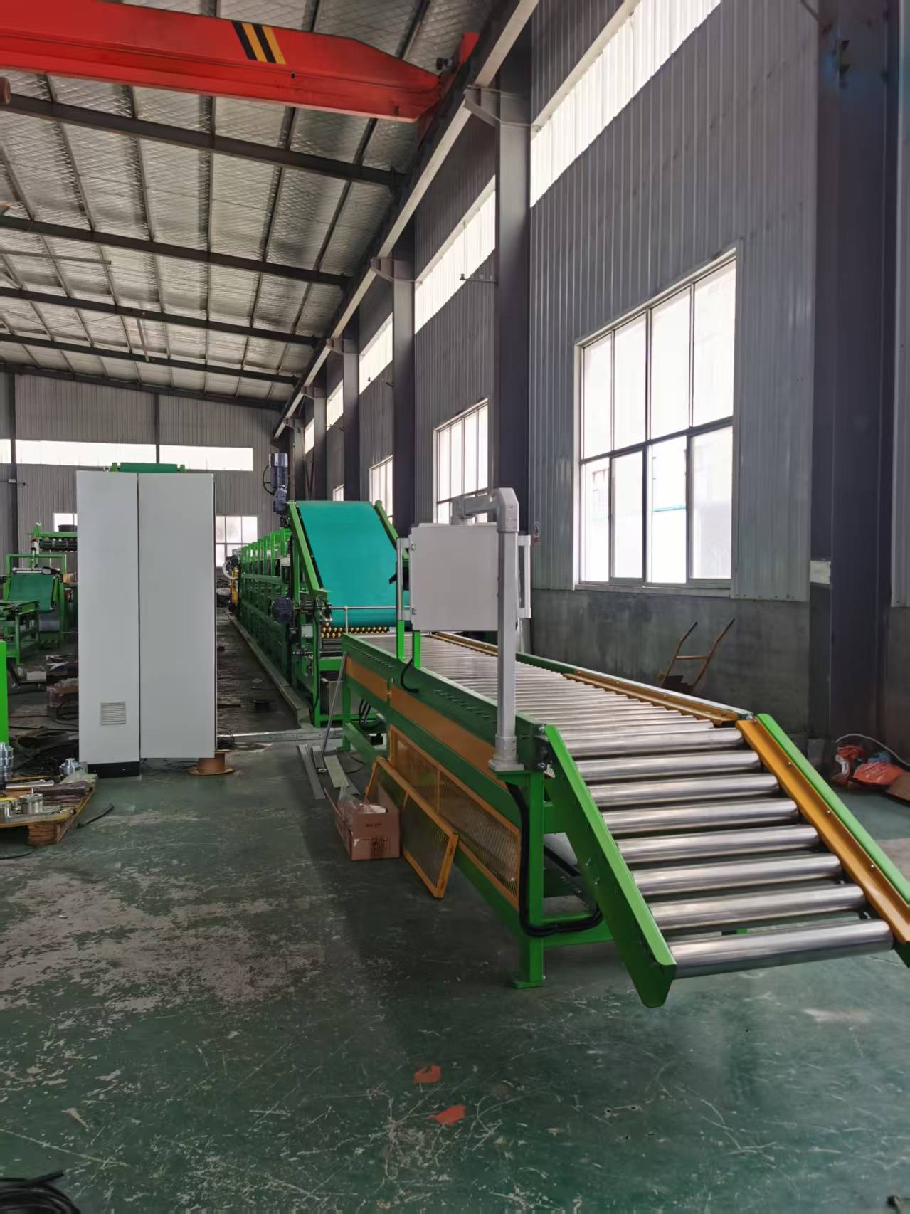
Every extra minute a rubber tread spends cooling is a minute of throughput lost—and every degree of uneven cooling shows up later as scrap or warranty claims. Most lines accept this as an unavoidable trade-off. AUGU AUTOMATION doesn't. Our rubber tire tread cooling production line solutions are engineered to stabilize tread dimensions faster and more uniformly, so you can push line speeds without pushing quality out the door. Here's what changes when cooling stops being a bottleneck and starts being a control point.
Why Tread Cooling Often Creates More Defects Than the Extrusion Step Itself
The extrusion step runs inside a relatively narrow process window. Screw speed, barrel temperatures, feed rate, and die geometry are all set before the rubber ever leaves the head. Most gross defects show up immediately at the die lip and can be corrected on the spot. Once the tread enters the cooling line, that control disappears. Water temperature, spray nozzle alignment, belt speed, and even plant humidity start to influence the rubber in ways no operator can fully predict. The surface cools and shrinks faster than the core, creating a thermal gradient that pulls the tread into subtle waves or width variations. Those flaws rarely show up at the cooling exit, but they are already locked in.
Water contact itself introduces problems the extrusion step never has to deal with. Hot extrudate is dense and homogeneous; when it passes under spray bars or through a dip tank, the outer skin opens just enough to trap moisture in micro-voids. That trapped water later flashes to steam during curing, leaving blisters or ply separations that get blamed on the press. Poorly aimed air knives add another variable. A single misaligned nozzle leaves a cold streak down the center of the tread, changing tack and creating a weak spot for splice adhesion. The extrusion step has no equivalent failure mode because it never subjects the rubber to a liquid phase transition.
The most damaging outcome is residual stress. Rubber leaving the die is still plastic enough for chain orientation to relax. Rapid cooling freezes that orientation before it can settle, storing energy inside the tread. Days later, that energy releases as dimensional rebound or splice pullback. The cooling line looks passive, so it rarely gets the same attention as the extruder. But the defects born there only become visible after the tread has already been cut, assembled, and cured, which makes correcting them far more expensive.
Precision Spray Patterns That Match Contoured Tread Profiles
Most spray systems treat every tire like a flat slab, blasting coating in wide, unfocused fans that pool in the grooves and starve the raised edges. That mismatch becomes obvious the moment you look at a worn tread block under magnification: the shoulders stay thin while the valleys run thick. A better approach starts with nozzle geometry modeled from the actual cross-section of the tread. Each spray pass follows the contour, varying droplet size and fan width so the coating lands evenly on every slope, lug face, and sipe wall. The result is a film that wears uniformly instead of flaking off the high points first.
Contoured profiles demand more than just a narrower fan angle. The spray pattern needs to shift in real time as the tire rotates, compensating for the way the tread opens and closes under load. Many coaters achieve this with a synchronized array of small-orifice tips set at staggered angles, each one covering a specific band of the profile. The overlaps are tuned so there is no heavy seam between passes. For deep, aggressive tread blocks, a secondary misting pass fills the shadow zones behind the lugs, preventing dry spots that later turn into rust or cracking.
Field adjustments matter just as much as the initial setup. Operators who regularly switch between highway ribs and mud-terrain lugs will dial in different pulse frequencies and tip distances, sometimes even swapping out the nozzle manifold for a contoured insert. That kind of flexibility keeps the coating from building up on the leading edges while leaving the trailing edges bare. It is the difference between a spray system that merely covers the tire and one that actually follows its shape.
Rethinking Water Temperature Control for Consistent Rubber Crystallization
Natural rubber crystallization is rarely a simple function of a single setpoint. Even when the bulk water bath reads a steady temperature, the thin boundary layer around the test piece can drift by several degrees, enough to shift nucleation rates and final crystalline fraction. Rethinking control means treating water temperature not as a fixed number but as a dynamic field that must be mapped against the rubber's own thermal history.
A common oversight is chasing tighter thermostat accuracy while ignoring circulation patterns and immersion depth. Slow-moving water or an oversized specimen can create stagnant pockets where the actual temperature deviates from the controller display. By measuring temperature at the rubber surface instead of only at the heater probe, operators often uncover a lag that explains inconsistent hardness and shrinkage results between batches.
The more useful approach couples water temperature control with real-time crystallinity proxies, such as optical clarity or stiffness change, rather than relying on fixed soak times. Adjusting the bath profile to compensate for the exothermic onset of crystallization can hold the driving force more constant. In practice, this means allowing the controller to anticipate thermal release instead of simply reacting after the fact—an idea that reframes temperature control as part of the crystallization process itself.
Line Speed Adjustments That Protect Tread Dimensions Without Sacrificing Output
Running a tread extrusion line faster almost always introduces dimensional drift, but slowing down to preserve profile accuracy leaves capacity underused. A better approach is to treat line speed as a continuously trimmed variable rather than a fixed recipe value. Closed-loop feedback from laser profile sensors or a weight-per-length scale feeds a control loop that nudges takeaway speed in fractions of a percent. These micro-adjustments keep the green tread within its width and gauge tolerance band while the line holds a steady high throughput.
The real difference comes from where the adjustment is applied. Instead of ramping the entire line up or down, speed changes are layered onto the haul-off and cooling conveyor zones with a slight delay compensation for shrinkage. The extruder screw speed and gear pump flow are adjusted in parallel so that mass output per meter remains constant. Because the correction window is small, the tread never sees the kind of sudden tension spike that pulls it out of shape.
This method preserves output by avoiding the usual stop-start or major slowdown cycles that come from manual correction. Operators can set a target production rate, and the system will ride just under the point where dimensional scatter starts to climb. In practice, a line running at 97–99% of its nominal maximum can hold tread width within ±0.15 mm, which is often tighter than what batch sampling achieves at lower speeds.
How Modular Cooling Zones Eliminate the Stop-and-Go Workflow
Traditional production lines often trap teams in a frustrating rhythm: start a batch, wait for it to cool, then rush to move it before the next step. That stop-and-go pattern kills momentum and burns out equipment. Modular cooling zones break this cycle by splitting the cooling process into independent, adjustable segments. Each zone can be tuned to a specific temperature range, so products move through continuously instead of piling up at a single chilling station.
The real difference shows up when you need to switch between product types. Instead of shutting down the whole line to recalibrate a massive cooling tunnel, you adjust only the zones that need it. A bakery running both dense sourdough loaves and thin baguettes can set one zone for slow, deep cooling and another for a quick surface chill. Operators tweak settings on the fly, and the line keeps rolling without the usual 20-minute pause for temperature changes.
What makes this feel less like a machine upgrade and more like a workflow redesign is how it handles small interruptions. If a downstream packer jams, the zones upstream hold their temperature instead of overcooling the product. Once the jam clears, everything resumes at the same pace. No more overcooked edges on the first batch after a restart, no more frantic sprints to clear a backlog. The line simply breathes, and the stop-and-go becomes a steady, predictable flow.
Seasonal Shifts in Cooling Water and What They Do to Rubber Memory
Rubber components in cooling systems rarely fail from a single dramatic event. Instead, they degrade through a slow accumulation of small insults, and seasonal temperature swings in cooling water rank among the most persistent. In cold months, water contracts and can cause localized pressure drops that pull air into the loop, while warmer months accelerate oxidation and soften the rubber matrix. These shifts alter how the material recovers after compression, and over time the memory that once kept seals tight simply fades.
The rubber's ability to spring back after being squeezed depends heavily on the thermal history of the water passing over it. Winter chill makes the polymer chains stiffer, so a gasket exposed to repeated cold starts develops micro-tears at stress points. Summer heat does the opposite, increasing chain mobility to the point where the rubber takes a permanent set. Neither condition announces itself loudly; the first sign is often a slow drip or a faint coolant smell around fittings that used to stay dry.
Operators often chase leaks by replacing hoses or tightening clamps, missing the fact that the real culprit is the seasonal rhythm itself. Tracking water temperature trends alongside seal compression set values reveals a pattern: the worst degradation occurs during transition weeks when daily highs and lows swing more than fifteen degrees. That thermal cycling, more than any absolute temperature, is what kills rubber memory. A fitting that survives a frozen night and a boiling afternoon may look fine on the outside while its internal resilience is already gone.
FAQ
Rubber compounds have narrow processing windows. If cooling is too fast, the tread surface can stiffen unevenly and create internal stresses that show up later as cracking or poor adhesion during tire building. If cooling is too slow, the line speed has to drop. Precise control keeps the tread within the correct temperature range for dimensional stability and lets downstream handling happen without distortion.
The usual route is to combine longer active cooling zones with better heat transfer rather than simply speeding up the conveyor. Using high-efficiency spray nozzles, chilled water loops, and forced-air drying stages removes heat faster per meter of line. Adding buffer accumulation between cooling and cutting also smooths out flow so short stops don't force the whole line to slow down.
Direct water spray cools quickly but can leave water spots or cause surface bloom if residue isn't managed. Air cooling avoids wetting but is less effective for thick treads. A staged approach works best: a fine mist or atomized spray for initial heat removal, followed by dry air to stabilize temperature and remove surface moisture before the tread reaches the take-off conveyor.
First, measure the current temperature profile along the line to find where heat removal drops off. Look at nozzle condition, water filtration, and whether the exhaust airflow is actually pulling moist air away. Often replacing worn nozzles and improving air movement delivers more gain than adding length. Also check the control system: if cooling setpoints are fixed rather than tied to line speed and compound type, that's a quick win.
Yes, by using variable-speed pumps and fans that match cooling demand to actual production rate. Heat exchangers can recover waste heat from cooling water for building heating or boiler feedwater preheating. Closed-loop water treatment reduces makeup water and keeps spray nozzles from clogging, which keeps heat transfer efficiency from degrading over time.
Uneven cooling leads to variable shrinkage and stiffness along the tread length. When the tread is later applied to the carcass, those differences cause splice gaps, overlap, or unbalanced tires. Uniform cooling ensures consistent geometry and green tack, so tire building machines run with fewer adjustments and scrap rates stay low.
Modern lines tie coolant temperature, spray intensity, and conveyor speed to the specific compound recipe and current ambient conditions. Sensors feed real-time surface temperature data back to the PLC, which adjusts cooling stages automatically. This reduces operator intervention and prevents the set-and-forget drift that causes off-spec tread batches.
Conclusion
Tread cooling frequently introduces more flaws than extrusion because water application is treated as an afterthought. Uneven quenching triggers residual stress, warpage, and surface defects that only surface later. Precision spray patterns that follow contoured tread profiles reduce this by eliminating dry spots and localized overcooling. Instead of flooding the entire section, targeted nozzles adjust coverage to rib height and groove depth, so every part cools at a comparable rate. Rethinking water temperature control also matters: maintaining a narrow band around the rubber's crystallization range stabilizes shrinkage and prevents memory effects that distort tread dimensions. Without this, operators chase dimensional drift with line speed changes, which rarely fixes the root cause.
Line speed adjustments can protect tread geometry if they are coupled with cooling zone logic rather than applied globally. Modular cooling zones allow sections to run at independent rates, so brief slowdowns for thickness changes do not force the whole line into stop-and-go behavior. This keeps throughput high and avoids the thermal cycling that damages rubber memory. Seasonal shifts in incoming cooling water temperature also need compensation, as warmer summer water slows heat removal and colder winter water can overcool the surface and trap heat inside. A well-designed system monitors delta T across each zone and trims flow or temperature proactively. The combined effect is fewer rejects from dimensional variation, faster stabilization, and a production line that holds its quality targets without constant operator intervention.
Contact Us
Contact Person: Lareina
Email: [email protected]
Tel/WhatsApp: +86 17561696737
Website: https://www.auguauto.com/