

Top EMI Filter Solutions for Reliable Electronics
2026-10-10
Electromagnetic interference can turn a well-designed circuit into a source of frustration—random glitches, failed compliance tests, or mysterious resets. The right EMI filter does more than suppress noise; it protects signal integrity and extends product lifespan. In this guide, we explore top filter solutions that balance performance, size, and cost, drawing on real-world insights from DOREXS and other industry leaders. Whether you're tackling conducted emissions on a power line or cleaning up a high-speed data bus, you'll find practical options worth considering.
The Hidden Threat of Conducted Emissions in Dense PCB Layouts
In tightly packed boards, every trace and plane edge becomes a possible conduit for noise. Conducted emissions don't radiate directly, but they ride on power and signal lines, escaping through connectors and cables. As spacing shrinks, parasitic coupling between adjacent traces and overlapping planes rises sharply, turning a seemingly minor switching transient into a system-level failure.
The root cause often hides in shared return paths and fragmented reference planes. High-speed return currents follow the path of least inductance, but in a dense layout that path may cross splits, jump layers through vias, or merge with noisy power returns. This creates common-mode voltages that drive cables like antennas. Decoupling capacitors placed without considering their loop area can make things worse by injecting switching noise directly into the ground structure.
Designers need to treat conducted emissions as a layout problem, not just a filter add-on. Keeping return paths continuous, minimizing plane splits under critical signals, and placing filtering at connector boundaries are more effective than chasing emissions after the fact.
Why Common-Mode Chokes Are Not a One-Size-Fits-All Fix
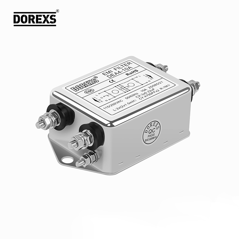
A common-mode choke looks simple—two windings on a core—but the impedance it presents to common-mode noise changes sharply with frequency. A part rated 10 mH may only provide that inductance below a few hundred kilohertz; with just 75 pF of interwinding capacitance, it self-resonates around 184 kHz. Above that point, the choke becomes capacitive and stops blocking common-mode current, leaving the circuit unprotected where emissions often peak.
Current and core material further limit the “universal” approach. Ferrite cores saturate when common-mode current or DC bias exceeds a threshold, and once saturation begins, the effective inductance can drop by orders of magnitude. A choke that works perfectly on a 2 A data line may be nearly useless on a 10 A power rail, not because of the wire gauge, but because the core no longer stores magnetic energy the same way. Winding geometry also creates leakage inductance, which appears as a series differential-mode component that can ring with nearby capacitors and make conducted noise worse in a narrow band.
Even the board layout and source impedance change how a choke behaves. If the common-mode source impedance is very low or very high, a choke with the wrong impedance profile can reflect or pass noise instead of dissipating it. Two designs with identical power levels and cable lengths can need completely different chokes—one with a nanocrystalline core for low-frequency attenuation, another with a small ferrite bead for high-frequency damping. Without measuring the actual noise spectrum under load, picking a choke by voltage and current rating alone is closer to guesswork than engineering.
Material Choices That Quiet Down Switch-Mode Power Supplies
Ferrite selection plays a bigger role than many designers expect. A high-loss nickel-zinc core placed near the switching node can absorb the sharp energy from ringing that would otherwise radiate across the board. Manganese-zinc ferrites, on the other hand, work better for lower-frequency conducted noise, especially when shaped into beads or sleeves around gate-drive traces. The trick is to match the material's loss peak to the actual oscillation frequency, rather than grabbing whatever bead happens to be in the library.
Capacitor dielectrics also shape the noise floor in ways that circuit diagrams rarely show. Polymer electrolytics and multilayer ceramics with low equivalent series resistance flatten the ripple voltage, but their mechanical resonance can introduce audible tones if the case isn't damped. Choosing a capacitor with a slightly higher ESR often tames resonant peaking at mid-frequencies, while a parallel film cap handles the high-frequency edge. The physical placement and lead length matter as much as the part number, since a few millimeters of trace inductance can undo a carefully selected capacitor.
Shielding materials round out the quieting strategy. Conductive elastomers and metalized fabrics create low-impedance return paths for common-mode currents that would otherwise escape through seams and connectors. Absorber sheets made from carbonyl iron or ferrite-loaded polymers can be cut to fit over hot spots like the transformer gap or the switch heatsink, turning radiated fields into tiny amounts of heat. These materials are not a substitute for good layout, but they can knock down the last few decibels that separate a noisy board from a quiet one.
Integrating EMI Filters Without Destroying Signal Integrity
Placing an EMI filter directly in a high-speed signal path often feels like a tradeoff: tame the emissions, but watch eye diagrams collapse. The trick is not to fight the filter but to make it part of the impedance profile. A ferrite bead with the wrong current rating saturates under load and starts looking like a nonlinear resistor, while a capacitor with too much parasitic inductance just moves the resonance somewhere else. The usual fix is to match the filter's cutoff so far above the signal bandwidth that its phase ripple barely touches the fundamental, then let downstream termination absorb any residual reflections.
Layout matters more than component values here. A tiny pad discontinuity or a via stub under the filter can introduce more jitter than the noise you are trying to remove. Run the filtered trace over an uninterrupted return plane, keep the filter components tight to the pin, and avoid sneaking a ground pour underneath the bead—that creates a coupled path that bypasses the filter entirely. If the signal is differential, apply the same filter to both legs and verify the common-mode choke's leakage inductance does not push the differential impedance out of spec.
Automotive-Grade Filtering Under the Hood and Beyond
Most drivers never see the abuse a filter takes under the hood. Heat cycles past 150°C, constant vibration, and oil mist loaded with soot and metal fines would shred a standard paper element in weeks. Automotive-grade filters earn their name through layered synthetic media, precise pleat spacing, and relief valves that keep oil flowing even when the element is clogged—decisions driven as much by warranty claims as by lab tests.
Yet the really demanding work often happens beyond the engine bay. Transmission filters trap clutch material in fluid that never gets changed on many modern cars, while diesel fuel filters separate emulsified water before it reaches high-pressure injectors. Crankcase ventilation systems use coalescing media to return oil droplets to the sump instead of coking intake valves. Coolant filters—still rare outside heavy-duty fleets—are quietly becoming necessary as OEMs pack more heat exchangers into smaller spaces.
The next shift is not just finer media but smarter integration. Differential pressure sensors flag a loaded filter before bypass opens, while some EV thermal loops now use ion-exchange filters to keep battery coolant conductivity low. Under the hood or buried in a skateboard chassis, the filter is becoming a monitored component, not a forgotten maintenance item.
Testing Real-World Attenuation: What Datasheets Won't Tell You
Laboratory attenuation figures are typically measured under conditions that rarely survive contact with an actual job site. A material may be tested in a controlled reverberation room, mounted perfectly flush with no penetrations, and surrounded by massive, well-sealed barriers. In a real wall or floor assembly, you have electrical boxes, duct runs, pipe penetrations, and imperfect perimeter caulking. Each of these creates a flanking path that can easily drop the effective transmission loss by five to ten decibels below the datasheet number. A soundproofing assembly rated at STC 55 on paper might behave more like an STC 45 once the drywall crew is finished with it.
Low-frequency performance is especially prone to exaggeration in published specs. Small sample testing often lets a material show its mass-law behavior without the boundary conditions that damp or shift resonances in a larger assembly. Real rooms have studs, fasteners, and constrained edges that can create coincidence dips or structural resonances right where traffic rumble, machinery, or deep voices live. Datasheets rarely show the full transmission loss curve; they highlight a single-number rating that averages out the worst octave bands. If you are trying to block a neighbor's subwoofer, a material with a great overall number can still let 50 Hz through almost untouched.
The only way to know how an attenuation product will perform is to test it in a realistic assembly with actual noise sources. That means building a mock-up wall or floor with the same stud spacing, same layers, same outlet boxes, and same edge sealing you plan to use. Run a sweep from 40 Hz to 5 kHz and measure at multiple points, not just a single microphone location. Also pay attention to vibration paths: rigid connections between the noisy side and the quiet side will bypass the damping layer entirely. Even the best datasheet cannot account for the accumulated compromises of a rushed installation, but a few hours of field testing will reveal them with uncomfortable clarity.
FAQ
Focus on the frequency band where the noise is strongest—usually conducted emissions in the 150 kHz to 30 MHz range. The filter's insertion loss curve matters more than datasheet marketing numbers, and you'll want enough current headroom so it doesn't overheat or saturate under load.
They block common mode noise traveling on both lines without choking differential signals. In practice that means fewer random resets and sensor misreads when motors or relays switch nearby, so the equipment keeps running through noisy conditions.
Yes, when you're dealing with high-frequency leakage into a shielded enclosure. They provide very low inductance to ground and can tame ringing that ordinary surface-mount caps miss, which often saves you from chasing mysterious failures later.
Ferrite beads are a quick, low-cost fix for localized high-frequency noise on a single trace. They won't replace a proper filter for broadband conducted emissions, but they can clean up a clock line or gate driver without adding much bulk.
Patient monitors and infusion pumps often sit next to other life-critical equipment, so interference isn't just an annoyance—it can corrupt data or affect therapy delivery. Filters in these designs must meet tougher IEC 60601 standards and still work after years of use.
A single-stage filter is fine for modest noise reduction, but a two-stage setup adds a second LC section for steeper attenuation. You'd step up to two stages when emissions are stubborn or the load itself generates a wide spectrum of noise.
To some extent, yes. Keeping loop areas small, routing noisy traces away from sensitive inputs, and using solid ground planes lowers baseline noise so your filter doesn't have to work as hard. But layout alone rarely eliminates the need for filtering on power entry points.
Capacitors and magnetics in filters change over time and with heat, which can shift attenuation at certain frequencies. Choosing components rated for the actual operating temperature—not just room temperature—and avoiding cheap electrolytics helps maintain filtering over the product's lifespan.
Conclusion
Conducted emissions rarely announce themselves until a prototype fails EMC compliance or a field return lands on the bench. On densely packed boards, switching noise couples through parasitic capacitance and ground bounce, turning short traces into unintended antennas. The first instinct is often to drop in a common-mode choke, but the impedance curve and saturation behavior matter as much as the inductance value. A choke that works at 100 kHz can be nearly useless at 30 MHz where the real narrowband spikes live. For switch-mode supplies, ferrite selection and winding geometry often do more than adding more capacitance. Low-loss NiZn cores can suppress high-frequency ringing without cooking themselves, while nanocrystalline cores handle lower-frequency differential noise with better thermal headroom.
The harder problem is placing filters without wrecking signal edges. A poorly damped LC stage can ring worse than the noise it was meant to remove, corrupting USB, Ethernet, or CAN transceivers. Start with small, lossy ferrite beads on power rails and use CLC or pi filters only after measuring the actual impedance looking into the load. In automotive designs, everything from a window motor to an ADAS camera shares the same harness, so filters must survive load dump, reverse polarity, and continuous vibration. Finally, datasheet attenuation plots are usually taken with 50-ohm source and load impedances, which almost never match reality. Building a simple LISN and testing the filter in situ reveals leakage paths, layout parasitics, and resonance shifts that no vendor graph will show. Reliable electronics come from matching the filter topology to the real impedance, not from chasing the highest insertion loss number.
Contact Us
Contact Person: Eric
Email: [email protected]
Tel/WhatsApp: 8618117837140
Website: https://www.emcdorexs.com